
What is Design for Assembly?
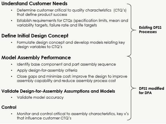
In previous articles we covered design for six sigma and design for lean. Now let’s take a look at Design for Assembly. We’ll do this by following the Design for Six Sigma (DFSS) thought process, and add design for assembly (DFA) subtopics as follows:
Recall the objective of DFSS/DFA is to model and improve design performance before manufacturing the part, even before creating a prototype. DFA therefore requires assembly performance to be assessed and modeled in a way that can determine (while still in the design phase), assembly performance enhancements.
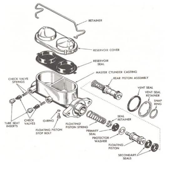
We’ll use a typical master cylinder assembly as an example. Note the exploded parts diagram helps to ‘make the process’ (or product) visible. Of course, 3D CAD systems are applicable here (as well as 3D printers, which could enable a physical trial of an assembly sub-process to be performed). We’ll also identify the base component and part assembly sequence:
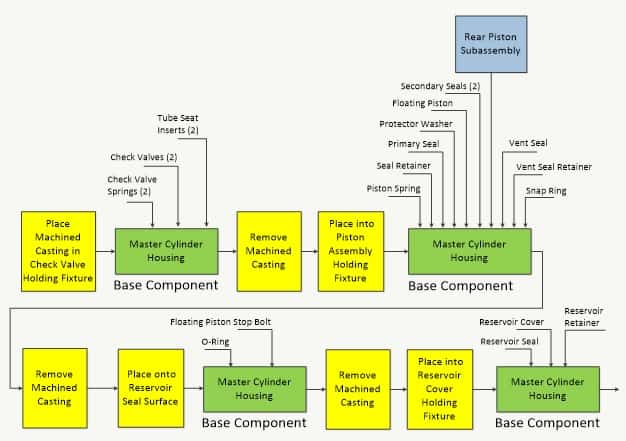
In this example, the base component (master cylinder housing) is placed in fixtures and parts are vertically installed. The base component re-oriented and placed into different fixtures several times throughout the assembly process.
Like any process map, the objective is to make the process visible. Also note the map can be used to estimate total assembly time/cost and to form a basis for a design for assembly P-FMEA (using a traditional P-Map).
With an exploded parts diagram, cross-sections and the assembly sequence, a list of design-for-assembly criteria can be applied, some of which is provided as follows:
- Assemble on a suitable base
- During assembly, is the base component oriented horizontally and lying ‘flat’?
- Can special fixtures to assist in assembly be eliminated?
- Are parts stacked vertically when installed into the base component?
- Layered assembly
- Does the design provide for easy insertion?
- Does the design provide for disassembly (including maintainability & service environments)?
- Mistake-proof and reduce assembly risk
- Can a part be improperly installed (upside-down or backwards)?
- Can a part be partially installed?
- Simplify and reduce the number of fasteners
- Eliminate screws, bolts, clips, rivets were possible
- Use snaps, interlocks, slots and press fits were possible
- Enable automatic tools to be used
- Limit flexible parts
- Eliminate wires, cables and belts were possible (or plug components together were possible)
- Modular and multi-functional parts
- Is the design of a component suitable for multiple applications?
- Can a component be designed for perform multiple function?
- Limit the number of parts
- Is there a reason for dissimilar materials to be used for mating components? If not, can they be combined into a single component?
- Design parts for feeding and insertion
- Is tangling of components minimized?
- Can automated equipment pick and place the part?
Of course, cross-functional team members can contribute to the criteria, the answers to the questions and the design thinking necessary to improve design for assembly. Cost models should show reduced cost with the improved assembly process. Also, when prototype parts are available we can validate our cost model and ensure the appropriate controls are in place which ensure robust assembly.
Finally, recall our overall DFSS/DFA objective to maximize customer value and minimize cost. Therefore, design and assembly process optimization should also ensure customer critical-to-quality characteristics aren’t compromised.