Validation / Systems Engineering (Part 3)
In Part 1 and Part 2 of this article series, we described validation engineering as the process of validating, monitoring and execution of product requirements to ensure customer needs are met. The validation engineer is the validation process owner and works with subject matter experts to develop complete, accurate and testable requirements.
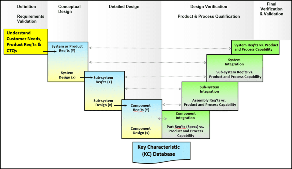
We proposed the following “V” diagram which illustrates the requirements validation and allocation as well as the corresponding integration and testing at each level:

In this article, will focus on subsystem design and component integration. A good example of a subsystem (or subassembly) might be a printed circuit board assembly (PCBA).
Note that a complex system may comprise of several sub-systems, or subassemblies, like PCBAs. This system breakdown structure is important to characterize early in product development.

Sub-System Design (x)
PCBA Design for Manufacturability – manufacturability of any subassembly design should be considered. In the case of PCBAs, manufacturers have DFM models by which the PCBA design files can be analyzed to identify potential manufacturability concerns.
PCBA Design for Test – facilitates design verification / component integration – ensure testability of the PCBA. Ideally 100% test coverage could/should be achieved, although certain limitations may exist.
PCBA Test Equipment Design – will you be able to test the PCBA once it’s manufactured? Co-development of PCBA test equipment should therefore be emphasized in the subsystem design phase of the product. (This is often overlooked or resources are often occupied with product design vs. test equipment design.)
Subsystem Fabrication
PCBA Fabrication / Post-Build Analysis – the PCBA is fabricated according to service-mount-technology best practices, usually including in-process inspections (automated optical inspection, x-ray inspection, etc). A post-build analysis should reveal any inadequacies in the manufacturing process.
Subsystem Modeling & Design Verification
PCBA Verification Testing – test equipment is ultimately developed to ensure validated requirements allocated to the “PCBA-level” are thoroughly tested and within specification limits. Also, since design performance was modeled via Y=f(x) and Sy=g(Sx,x), the question answered by integration / verification testing is: Are our models accurate?

This requires detailed knowledge of our transfer functions. An analytical design of experiments (DoE) would identify the transfer function Y = f(x) & critical “x’s” and a Monte Carlo analysis would model the impact of variability Sy=g(Sx,x). Using this mathematical model, as well as actual values of our design parameters (“x’s”), actual design performance can be compared with the modeled.
Using our PCBA example, usually success is declared upon successful verification testing of hardware. Of course, the root cause of an unsuccessful verification test may be inaccurate design modeling. Either way, consider leveraging verification testing to ensure model accuracy. Otherwise, design quality issues may continue to be propagated with inaccurate models.
Also, in our PCBA example, consider 100% test coverage as a fully comprehensive integration test (ie. all components integrated and full functionality exercised). Anything less may have an associated risk, for example, a PCBA may need to be removed and replaced from the system and debugged further.
(For your particular product system breakdown structure, replace “PCBA” with any selected subassembly with the considerations above.)
Recent Posts
Categories
- Agile (1)
- Change Management (2)
- Design for Six Sigma (3)
- Ideation (1)
- Lean Manufacturing (1)
- Lean Product Development (5)
- Maximizing Customer Value (3)
- Product Lifecycle Process (5)
- Project Governance (1)
- Project Management (9)
- Requirements Management (8)
- Roles and Responsibilities (3)
- Six Sigma (1)
- Supply Chain (1)
- Systems Integration (1)
- Uncategorized (12)
- Value Stream Management (5)
- Verification and Validation (6)
